IoT thermostat design part 2
| « Tooling and testing for Particle firmware | NVMe clamp for camera rig » |
It's been a while -- nearly a year -- since I posted Part 1 describing the thermostat design. Here, finally, is the conclusion.
Electronics
The electronics side of things has largely worked out the way I'd originally planned it. The schematic remains unchanged and the PCB isn't far from the initial place-and-route: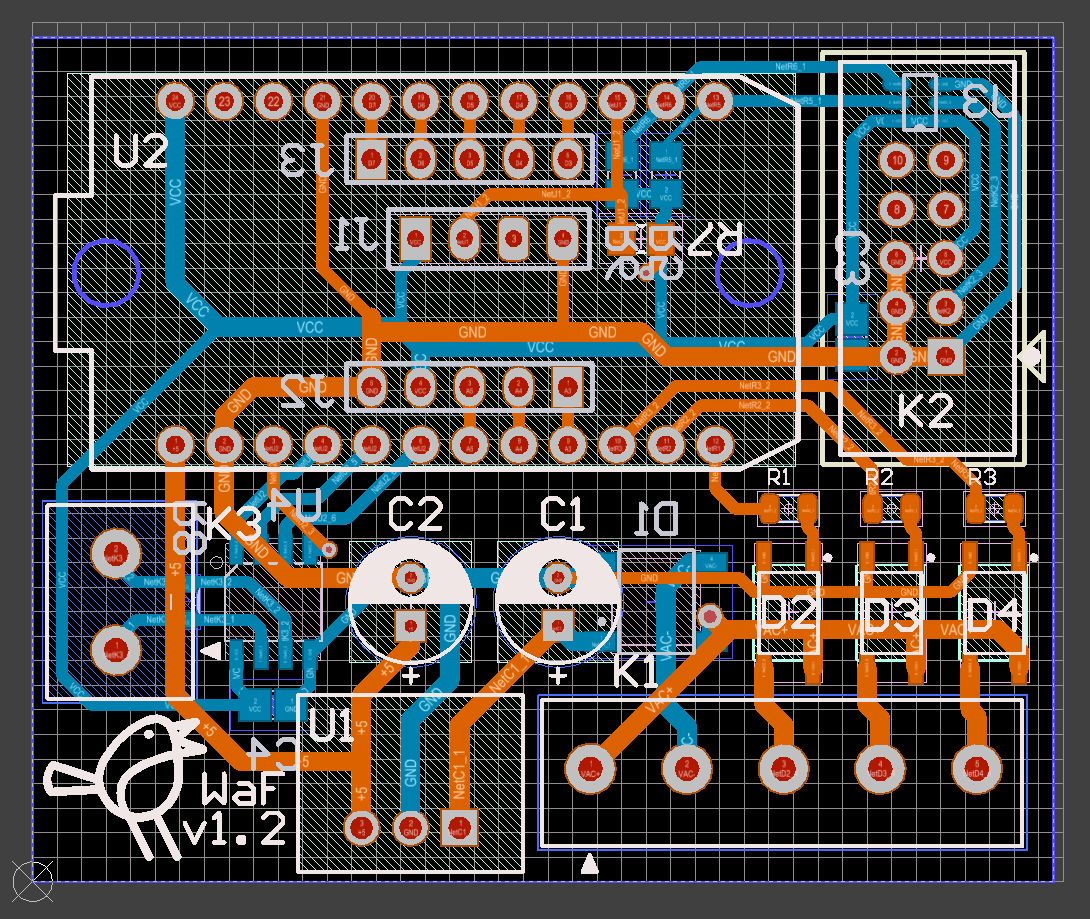
I made the mistake of sending the PCB off to get manufactured before I had all the components in front of me to place on a 1:1 printout to check pad sizes. Inevitably, one of the packages I'd had to define myself (for the TLP3122A solid state relay) I got wrong so it wouldn't fit. There wasn't even a particularly good reason for it - I just confused myself in the measurements.
Lesson learned: When designing custom SMT packages (or even if you aren't), dry fit your PCBs before manufacturing them.
The soldering process went great, though some of the boards needed some rework later on because an SMT pin here or there didn't quite catch the solder correctly. It's not clear to me why; it could be that solder mask slopped over a bit during board manufacturing; regardless:
Lesson learned: When designing custom SMT packages, consider making the pads a bit more generous than what the chip's specs suggest.
The somewhat frightening thing here is that Altium CircuitMaker runs a repository of part definitions contributed by the general public, and of course my custom package for the TLP3122A is now up there as well. I corrected the published version when the initial rev turned out to be flat wrong, but now I'm too lazy to page the oddities of working with CircuitMaker back into my brain to improve the functional-but-not-ideal version. So that kinda makes you wonder about what you're getting into when you're using parts defined by who knows what other clowns on the internet in your designs.
Packaging
Just because it looks nice...
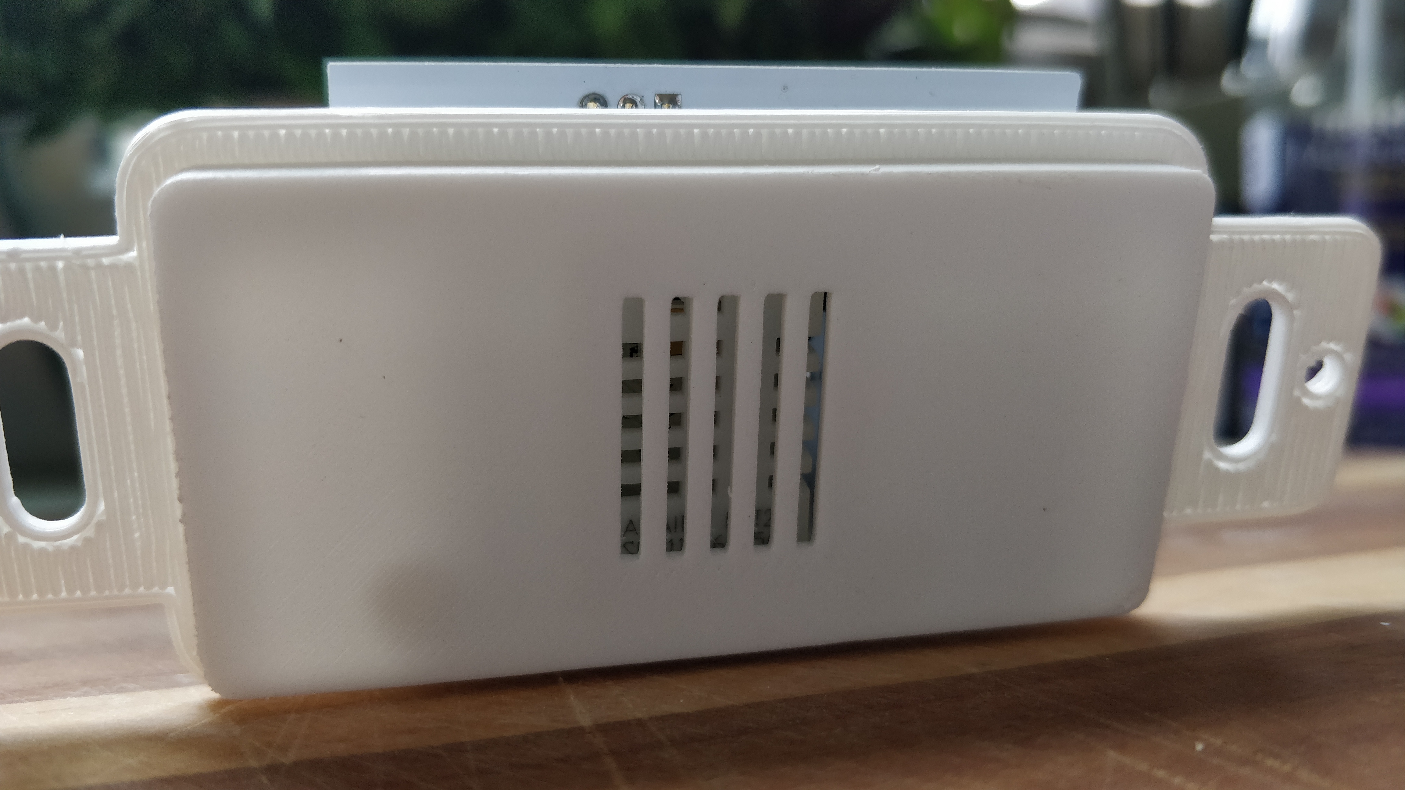
I designed a lovely insert for a Decora wallplate that stacked the big components in the back and exposed the DHT22 temperature and humidity sensor through a nice grille in the front.
I got it 3D-printed through CraftCloud with a turn-around time of about a week and a half. I only screwed it up and needed to re-print once (the receiving post for the plastic screw holding the PCB to the mount was too flimsy to have a thread tapped into it) and the quality of the prints was okay enough, at about $20 for 25 of these (plus $20 in shipping or so).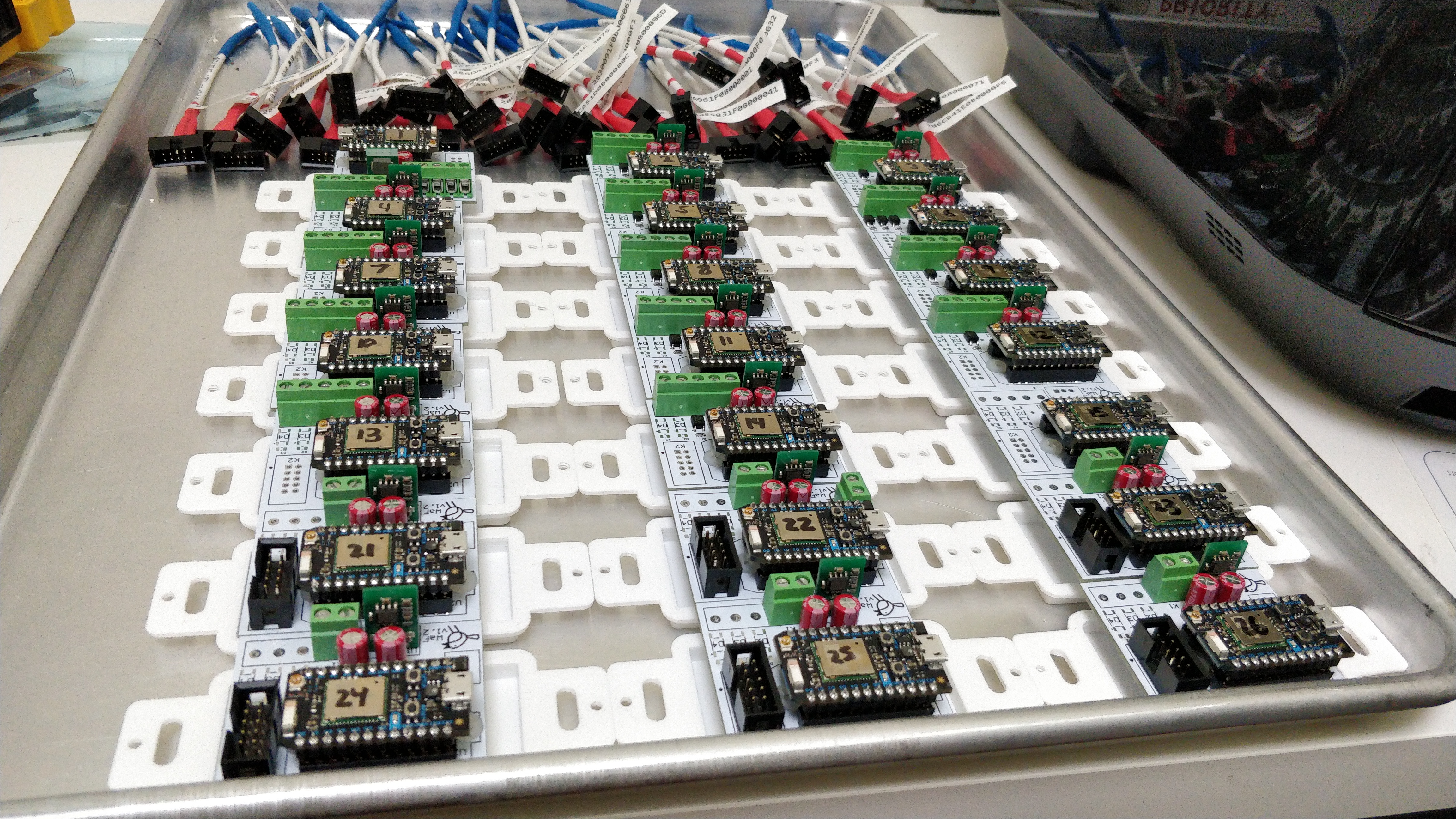
I enthusiastically assembled all the thermostats, installed the first five of them downstairs, verified that everything checked out, and went to bed.
(You can see where this is going.)
The next morning the downstairs was markedly colder than usual and all the thermostats reported a temperature about ten degrees higher than it should have been. Wat?
What even is temperature?
Next came a months-long journey of debugging why my temperature measurements were garbage when they'd worked so well on the breadboard test.
I set up a test rig next to my breadboard (thus controlling for temperature) with:
- a thermostat installed in a box, simulating the in-field devices
- a thermostat mounted to the 3D-printed mount but just not installed in a box, powered by 24VAC
- a thermostat mounted to the 3D-printed mount, powered via USB
- a thermostat not mounted to the 3D-printed mount, though still using the go-to-market PCB
- a thermostat using the go-to-market PCB but with the DHT22 sensor pulled away from the board
I took a week or so to build an initial version of my timeseries store and graphing code so I could track temperature readings over time.
I then pointed a big fan at my bank of thermostat variants until they all reported the same temperature and tracked how they regressed upward over the course of a few hours.
A few things became clear:
- Confining the DHT22 sensor into a fairly small space in the mount created two problems:
- It seemed to have reduced its access to freshly circulated air to the point that it had little hope of ever yielding accurate readings.
- Depending on how much you trust the internet, the DHT22 may perform some self-heating for the sake of humidity measurements, requiring significant air access to maintain accuracy.
- I'd stacked the DHT22 sensor on top of the bridge rectifier on the back of the PCB, and though the rectifier was doing just fine and operating within spec, it did give off enough heat to distort the measurements.
- Even the most extravagant variant with the DHT22 pulled away from the board still wasn't getting reliable enough readings.
So I had a stiff drink and pondered next steps.
I had basically lost trust in the DHT22's temperature readings and decided to call upon the venerable DS18B20 as the temperature sensor for the thermostats as well (since I was already using it for measuring radiant loop temperatures at manifolds). The boards already provided for a OneWire controller for the loop temperature sensors so I could populate that part (plus I2C pull-ups and buffer cap) on the thermostat boards as well and connect an off-board DS18B20. I kept the DHT22 around for its humidity readings and also just out of sheer curiosity.
Lesson learned: Designing one board instead of two different ones came about due to laziness but saved my ass in the end. Having escape hatches like a ready-to-go OneWire bus or (failing that) an exposed I2C bus in the PCB is really useful for dealing with unexpected eventualities like this. +++ would buy again.
Of course the DS2484 OneWire controller is the smallest and most difficult chip to solder on the entire board, and I'm now doing it as rework with other components nearby making it harder to access, and there are two 1608 SMT resistors inside the socket for the Particle board that need to added, so that was a bit special to do on fifteen boards. So it's all well and good to design a PCB that requires a thoughtful order of assembly until the moment that you need to rework stuff later on. Sigh.
Once I had the DS18B20 attached, another interesting problem emerged: it was impossible to get a good reading from it some time after the forced airflow was turned off. This turned out to be a combination of two more problems.
First, the black body of the DS18B20 soaked up radiant heat from the environment and thus did not provide a true measurement of air temperature as my amateur mind had hoped. The giant-pain-in-the-ass solution was to solder some ribbon cable to the sensor, heat shrink around all the pins, and then jam the sensor into a short (~3/4") piece of copper tube sized just right for the TO-92 sensor package and filled in with white heat sink compound (rather than silver or black, for obvious reasons).
Second, it seemed that even with the sensors exposed and packaged nicely on the DHT22 the readings were still a touch higher than what my breadboard would report. I unsoldered the DHT22 from all the boards and added a ~4" cable between it and the board, and that seemed to have closed the gap. I guess heat from the board, from the power supply stack and perhaps the Particle board itself, was either creeping into the sensor through its pins or just radiating onto it enough to distort the readings.
So that was the electronics side of things.
That packaging tho
Since the approach of putting it all into the wall wasn't going to work, I came up with a design for putting it onto the wall, just like every other thermostat on the market (no shit).
This was going to be a more protracted R&D process so I didn't want to spend $40 and two weeks' waiting on every iteration and decided to buy my own 3D printer. In the end I needed about twenty iterations so the math actually penciled out.
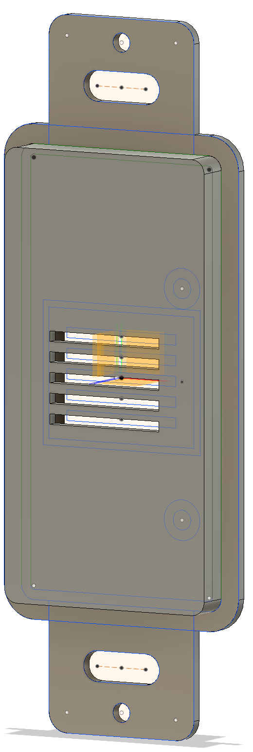
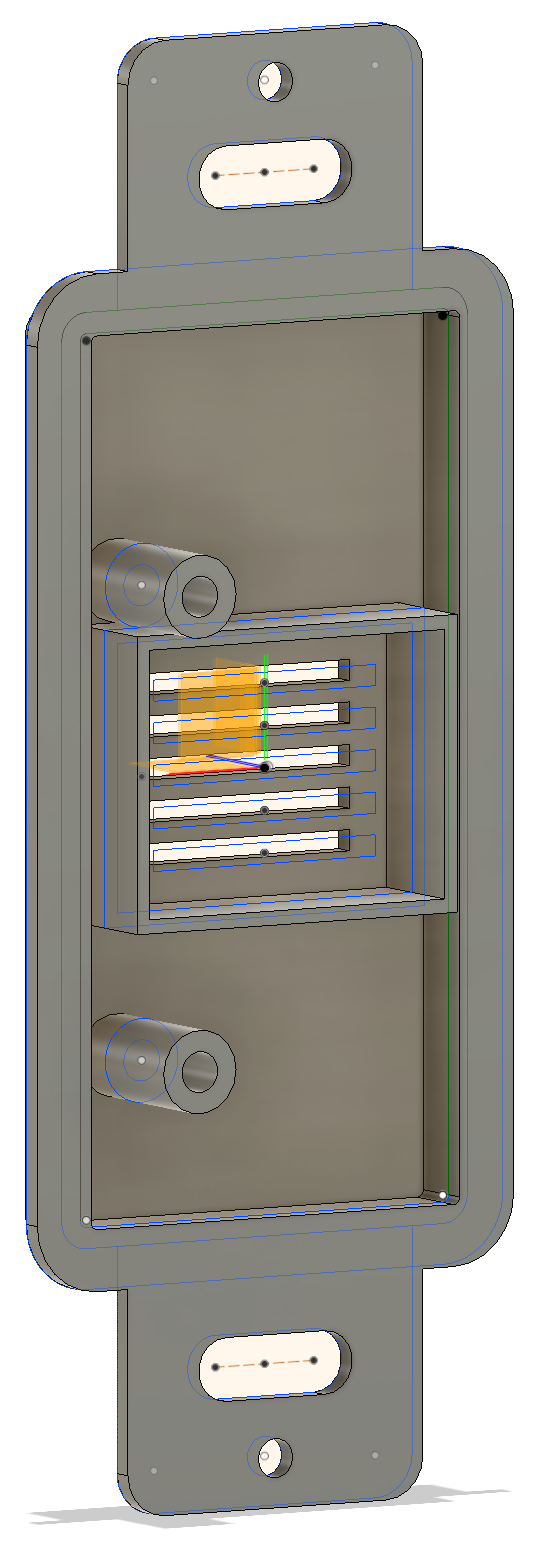
I designed a body that would carry the PCB in the back and have sides open to the air, complemented by a separately printed cover. This made the body easy to print (the big flat surface got to be on the bottom) and it made the cover easy-ish to print as well (by printing it upside down, with its "user-facing" flat surface face down on the build plate).
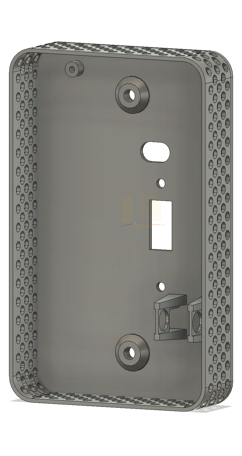
- The oblong and rectangular holes allow for the DS18B20 and DHT22, respectively, to be passed through from the back where the PCB lives.
- The two plain holes get tapped #6-32 to receive the plastic screws holding on the PCB (plastic so as not to mess with the WiFi antenna that one of them sits under).
- As a side note, PLA is eminently tappable provided you give it enough support (otherwise it just shears off).
- The vaguely pyramidal holes are used to attach the body to the in-wall box (so they're standard electrical device spacing) with the pyramiding acting as a bit of a washer.
- The small post on the top gets tapped #2-56 to mount the DHT22 through its top tab (which is really small, thus a #2 screw).
- The vaguely torii-looking gates on the bottom accept the copper tube that the DS18B20 is mounted in.
Here's a subset of the evolution of the body: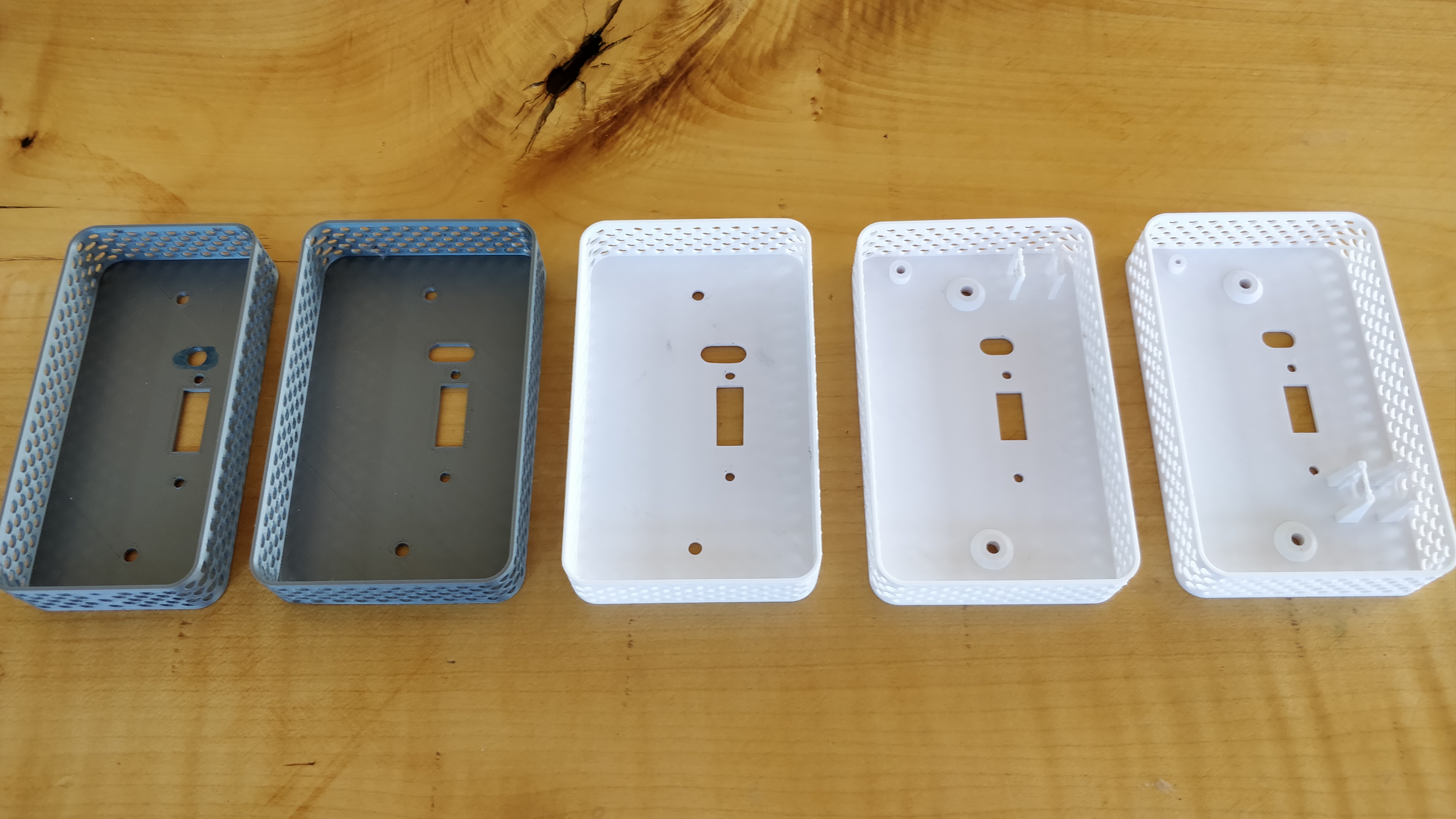
- On the left, I'd screwed up the dimensions as part of a general brain flub. Thankfully, parametric design in Fusion360 made this a fast fix.
- Next comes the final print I wanted to rough in before switching from the free PLA that came with the printer to the production-grade white PLA I'd bought for the project.
- Yup, white PLA prints fine.
- I've added the mounting post and gates for the DHT22 and DS18B20, respectively; however, the gates are too flimsy and break off easily.
- The go-to-market version.
Here's a bunch of them with the components installed; you can also see that I chewed the grille off the DHT22's in an attempt to maximize their airflow.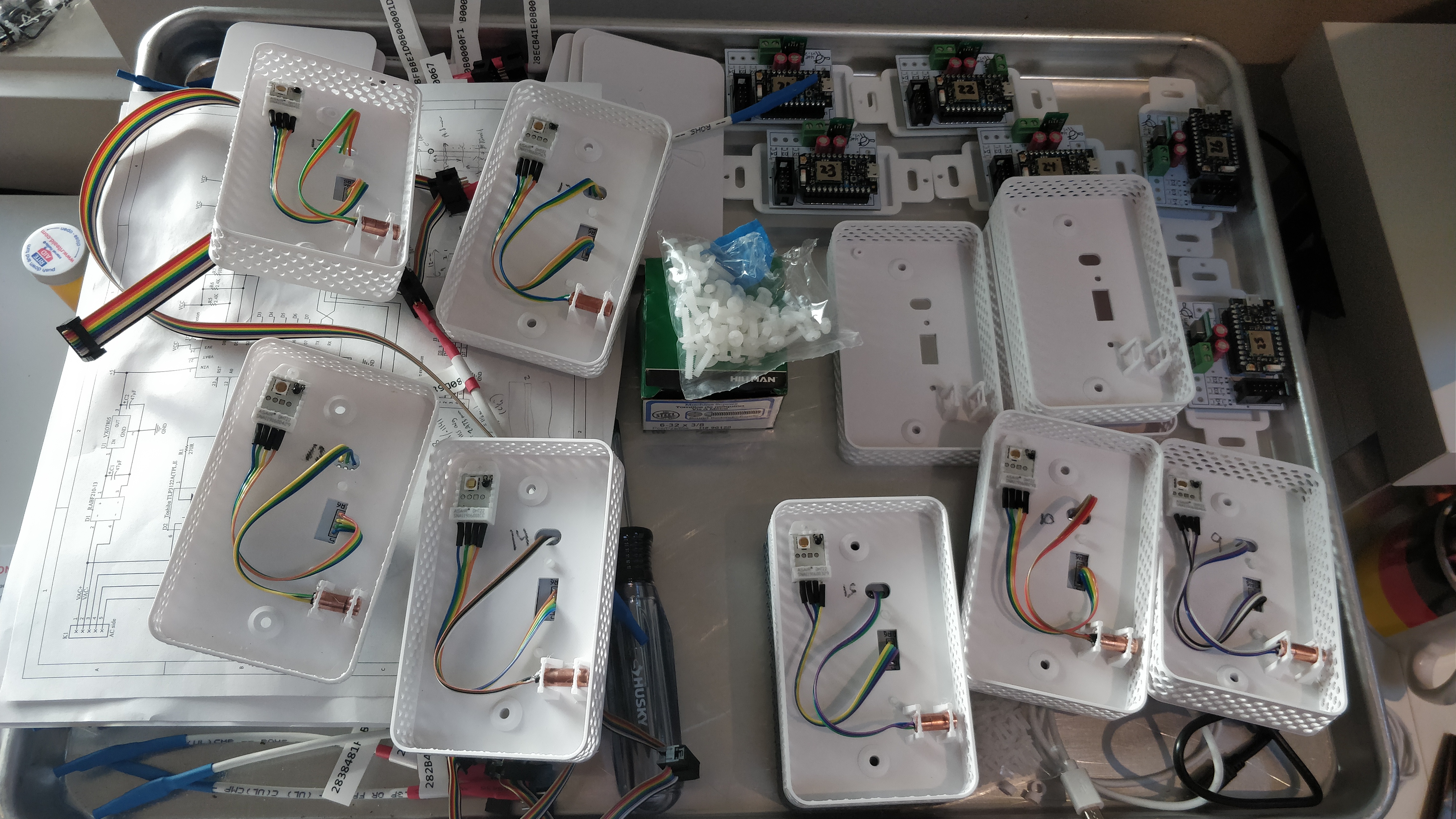
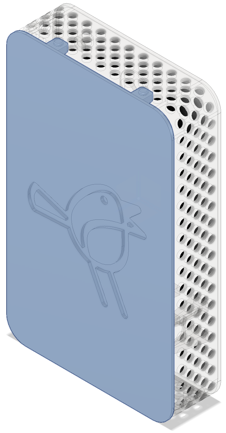
Up next came the design of the cover, which was also a convenient and cutesey branding opportunity for me and GRUMPYCORP.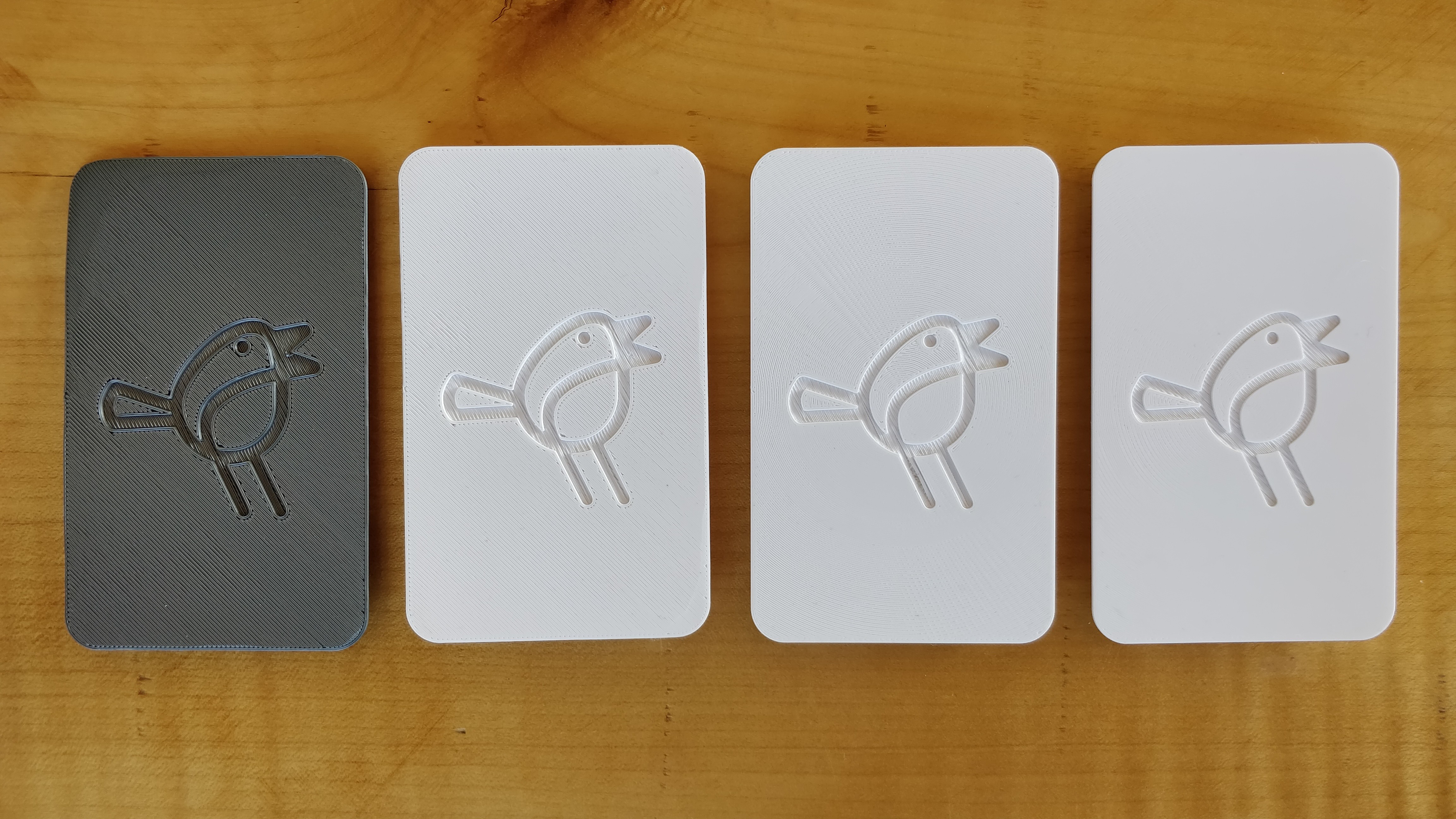
- The first cover came out pretty rough and partially lifted off the build plate. I corrected for this by raising the build plate temperature slightly and printing a thinner first layer.
- The second cover (now in white) came out pretty well but I wanted to do something niftier with the first layer pattern than the obviously 3D-printed diagonals.
- The third cover shows off the circular fill pattern that I liked the best of all the fill patterns.
- The fourth go-to-market version shows how much better it can get when tuning the first layer Z-height and the angle of the in-fill bridging at the back of the logo.
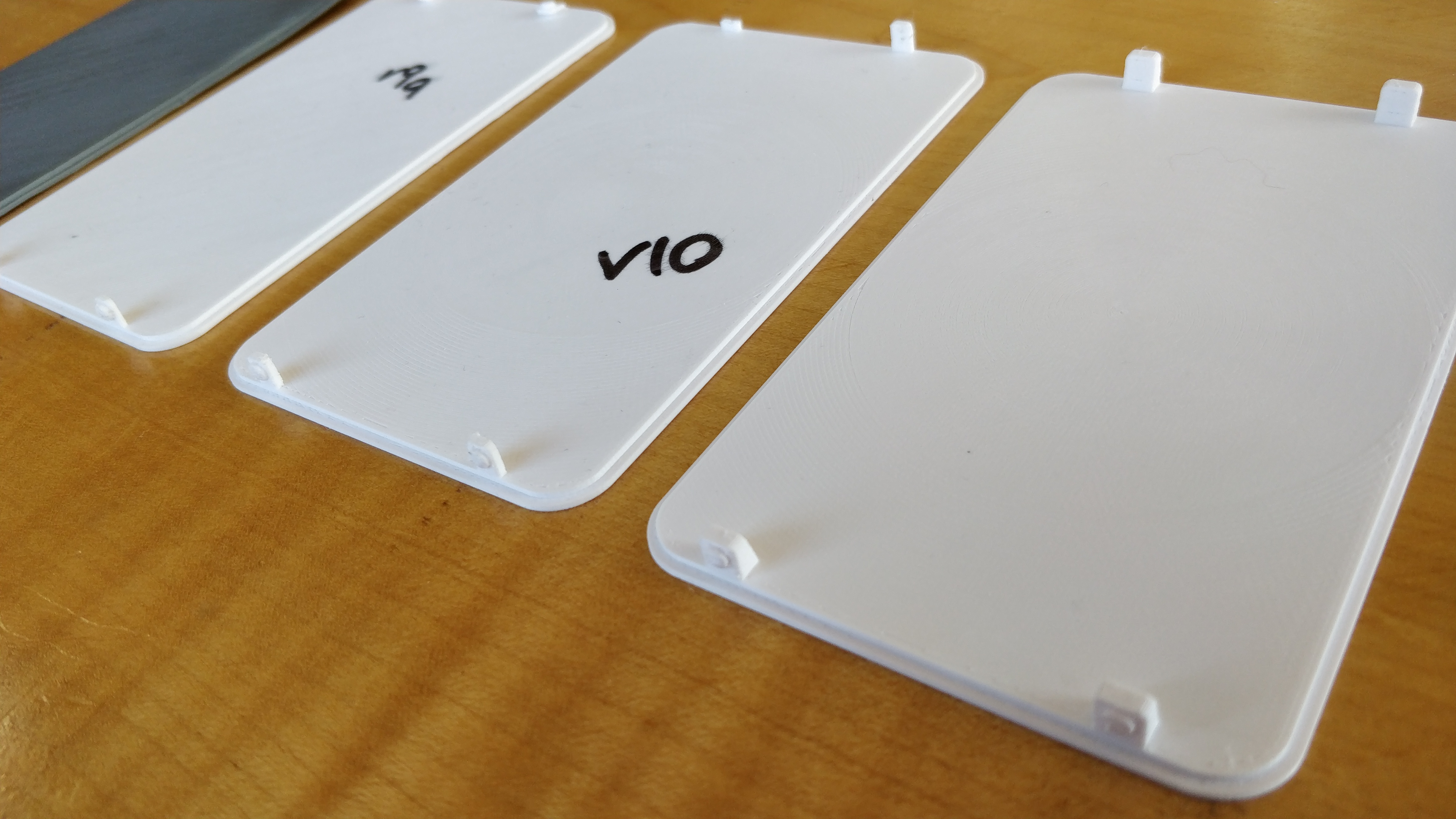
The cover is held on by pins that slot into the vent holes of the body. I initially figured I'd make the pins bendable for installing and removing the cover; however, PLA is more brittle than flexible so this ended poorly.
It occured to me that I can just warp the entire cover while installing it, rather than the pins, so the go-to-market version has reinforced pins that, rather than bending, can withstand the pressure put on them by warping the whole cover.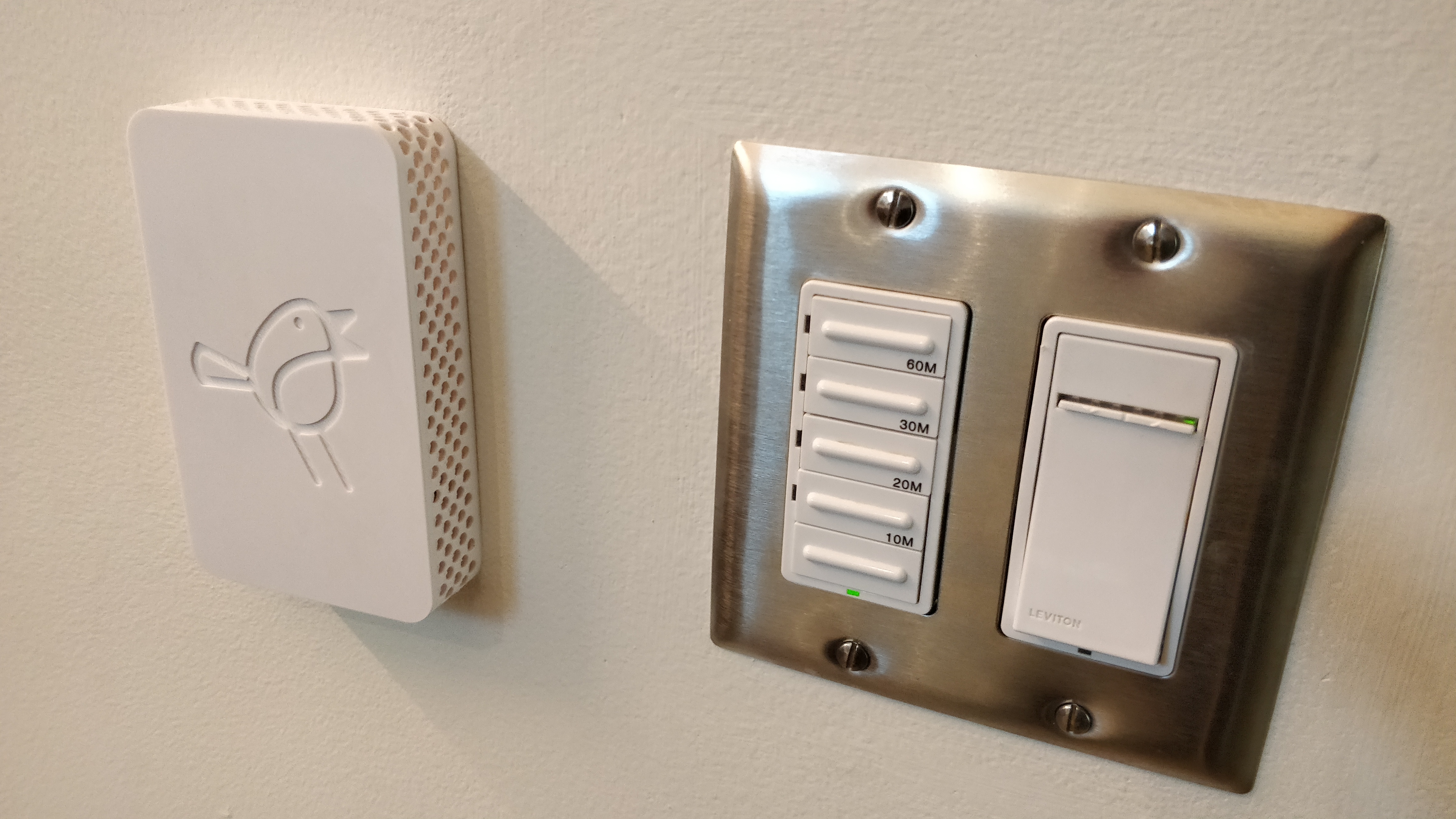
Of course there were two locations that had to be extra:
- The thermostat in the bandroom has to sit on top of the drywall because I don't want to cut a thermostat-sized hole into my nice acoustically treated sheetrock.
- The thermostat in the upstairs office is new and fulfills a reporting-only function, so there is no pre-existing hole in the drywall.
I whipped up a "back body" component that makes with the body and gives the necessary offset for the PCB and its components. For shits and grins I printed it with the silver PLA that came with the printer: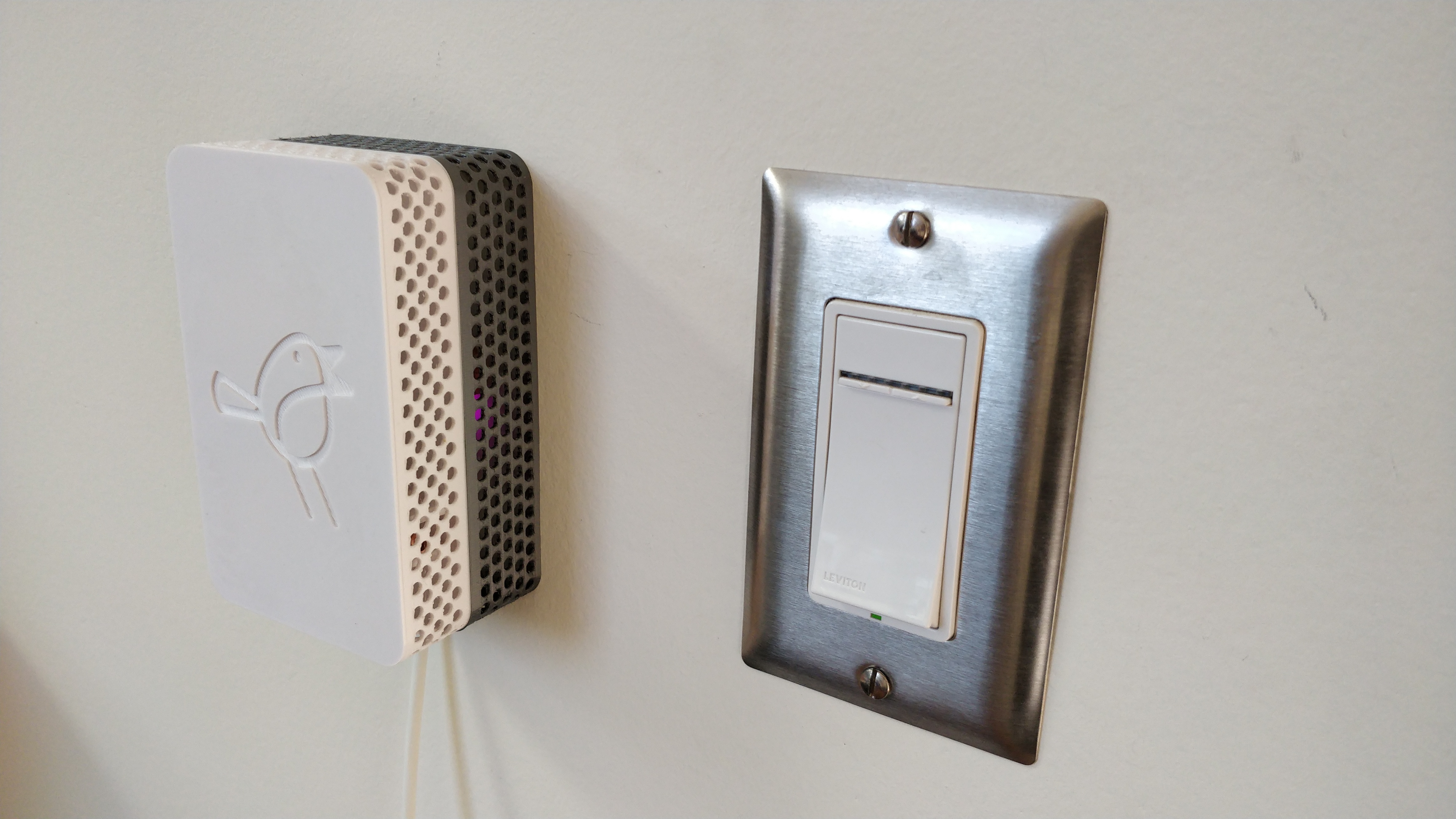
The print time for a pair of bodies was about nine hours and used $0.70 of filament per body. The print time for a pair of covers was about four hours and used $0.56 of filament per cover.
Missing features
There are some outstanding feature requests from our user base (a.k.a. my family); chiefly, they'd like to be able to inspect and adjust state on each device, rather than having to use a phone.
It's a reasonable and natural feature request; however:
- It's going to take a bunch of effort to create the electronics for this, e.g. using an I2C-based OLED display with buttons.
- It's going to take even more effort to figure out how to mount that dang thing on my precious covers which I'd now need to reprint.
- It's going to take some amount of firmware development.
- It kind of fucks up my architecture that sources all truth in the cloud.
All of this can be dealt with but I've got other things I want to take on next so this may take a while and/or never happen.
Lessons learned
3D printing
3D printing is pretty magical, but it's still an art form requiring significant intervention.
I spent the money on a Prusa MK3S kit since it was reported to be far lower maintenance than cheaper printers, and this has largely borne out. The Reddit community for Prusa has been a great resource and helped me resolve some early issues, like having to clean the bed with 99% isopropyl alcohol instead of the more common 70% IPA. Tools like PrusaSlicer and OctoPrint are quite capable, and I kind of love the PrusaSlicer UI that exposes gradually more settings as you go from simple (green) to advanced (yellow) to expert (red) mode: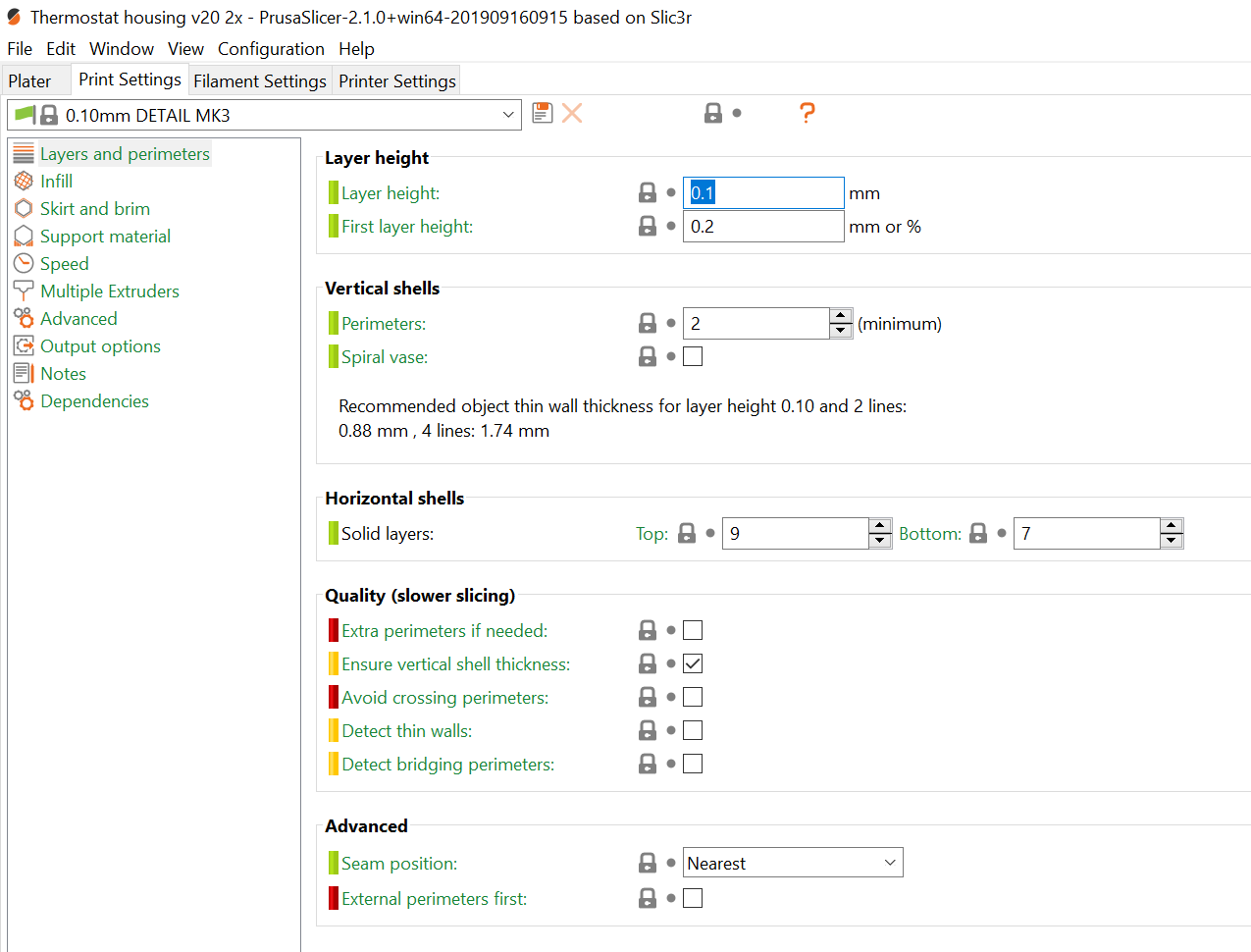
The defaults offered in simple mode are generally enough; I had to twiddle with some advanced settings for the cover but for the most part it was pretty straight-forward.
That said, there's no one right way to set up the system and it becomes an exercise in:
- visually fine-tuning things like Z-offset in five micrometer increments for appearance-quality parts like the cover,
- having to build cardboard moats around the printer so the print doesn't go wonky when the heatpump's air cirulator turns on, and
- establishing weird religious-grade rituals of cleaning and wiping the build plate just so in order to eliminate all dust and allow for perfect adhesion.
We're a far way from 3D printers being as dependable as regular printers, and we already know how printers were sent from hell to start with. It's an amazing micro-manufacturing capability to have, though my first response to any idea for something I could print is still "how is this going to go wrong and how many attempts will it take".
Designing for 3D printing
Fusion360 is made of magic and parametric design is my new best friend. I had to unlearn and invert pretty much every pattern I picked up over the years in AutoCAD, but it's worth it. I'm recommending Fusion360 as the design tool for things moving forward and look forward to getting to try it on some architectural (vs. manufacturing) work in the future (not that I need more projects).
Custom PCBs
Designing and manufacturing PCBs is really easy now, compared to doing it at home thirty years ago with my fingers in the etching bath, the tiny drill press, and all that. JLCPCB did a great job, and it was pretty easy to configure CircuitMaker for their design rules. +++ would buy again.
And to repeat the lesson from earlier in the post, always expose an I2C and/or OneWire bus for "oh shit" moments.
Next steps
This wraps the current push of posts for this phase of the project.
Up next:
- Get the radiant loop sensors installed.
- Improve the timeseries visualization capabilities and analyze heating decisions, loop temperatures, and so on.
- Get back to the next top-level goal of integrating with our security system to monitor open windows etc. - probably a project for the summer.
| « Tooling and testing for Particle firmware | NVMe clamp for camera rig » |